UV LED exposure unit
Published: July 2011
I've been building my own PCB exposure unit. As seen on lots of web sites the unit can be made from UV LEDs instead of traditional flueorsecent lamps. The unit is not finished at all, but I'll show the building and some comments about it. The unit is autmatic and has a programmable timer.
Materials
- UV LEDs: You can get UV LEDs at ebay, mine costed me 5USD and included 100 LEDs and 200 resistors (470 and 100 Ohms).
- Power source: I used two chinese USB chargers which cost 1.60€ each piece at some city store.
- Relay: This can cost some money, but you can find them everywhere. I preferred the relay solution instead of the transistor one.
- PIC16F88: It's cheap, little and has built-in timer, oscillator and ADC.
- Potentiometer: User frendly is a good choice.
- 3 7-segment LEDs or a 3 package: I used the 3 individual ones because I burned one LED of the 3 pack.
- 1 double switch (220V): Using double switch is mandatory. It has to disconnect the 220V source and the 5V PIC source. That caused me some problems, as you'll see.
- 2 push buttons: They need to be interfaed from the outside, so if you have a larger ones...
- Some misc stuff: resistors, a transistor (for the relay), a protection diode (for the relay too) and some pins to make your life easier.
Construction
I used a cardboard as a base. I drilled some holes and soldered together the LEDs separated by 1.75cm. I added some resistors. As I'm using a 10V source, the connection scheme is 2 LEDs and a 235Ohms resistor. I used 2 470Ohm resistor in parallel as I have plenty of them and soldered everything together. I used 80 LEDs in 2 LEDs units (2 LEDs + 2 resistors) which make 40 units. You can use the LED legs instead of cable to save materials. I need a photo here!
The box inside is black-painted to avoid reflections. I divided it in two zones: the circuit/interface zone and the exposure area. You'll have to do some holes, better ask for a Dremel! This is the result after some drilling work:
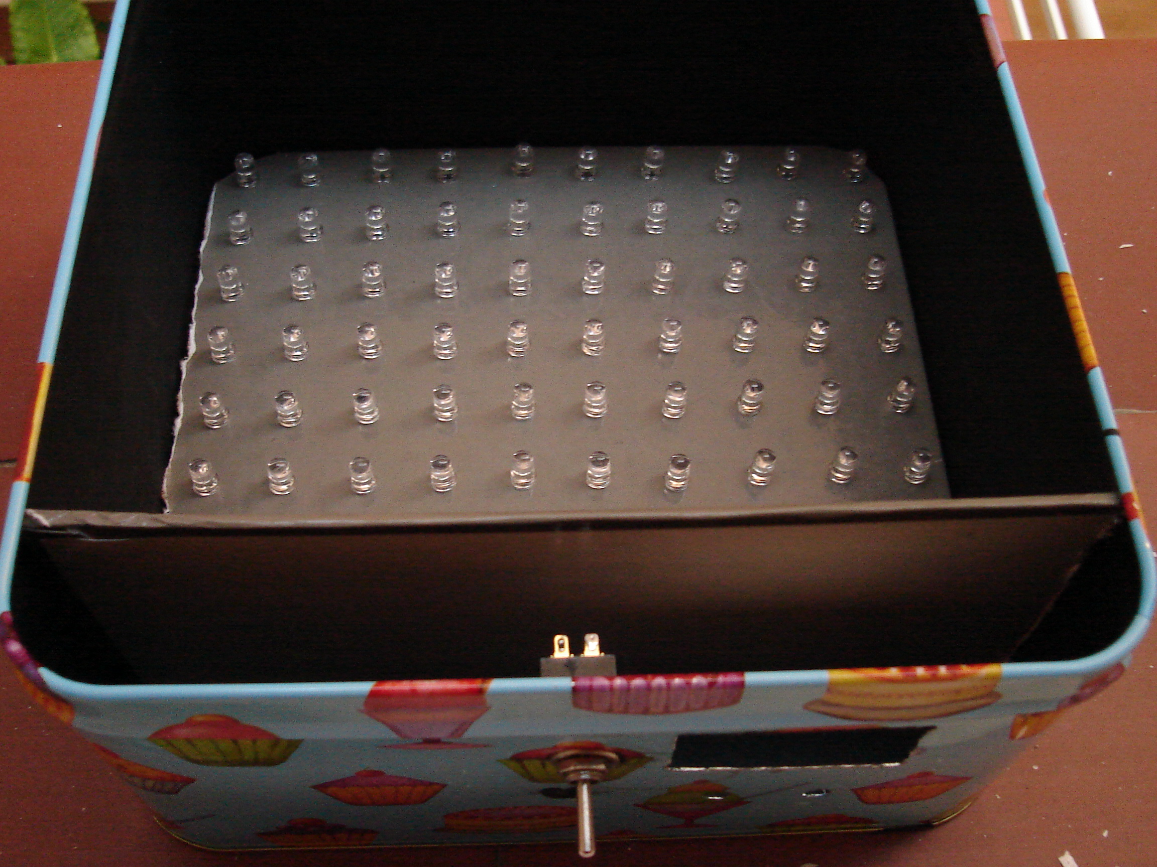
I drilled a hole for the LED screen, a hole for the switch, another one for the potentiometer and finally two more for the push buttons.
The timer
The digital circuit is quite simple. The PIC drives the display using the common trick of lighting one led at a time and switching them quickly so the eye doesn't catch the trick. It uses the ADC to determine the exposure time and save it to the internal EEPROM. The push buttons are used to save the ADC lecture and to start/pause/unpause the exposure. One more GPIO is used to activate the relay trough a transistor. I'll attach the schematic later.
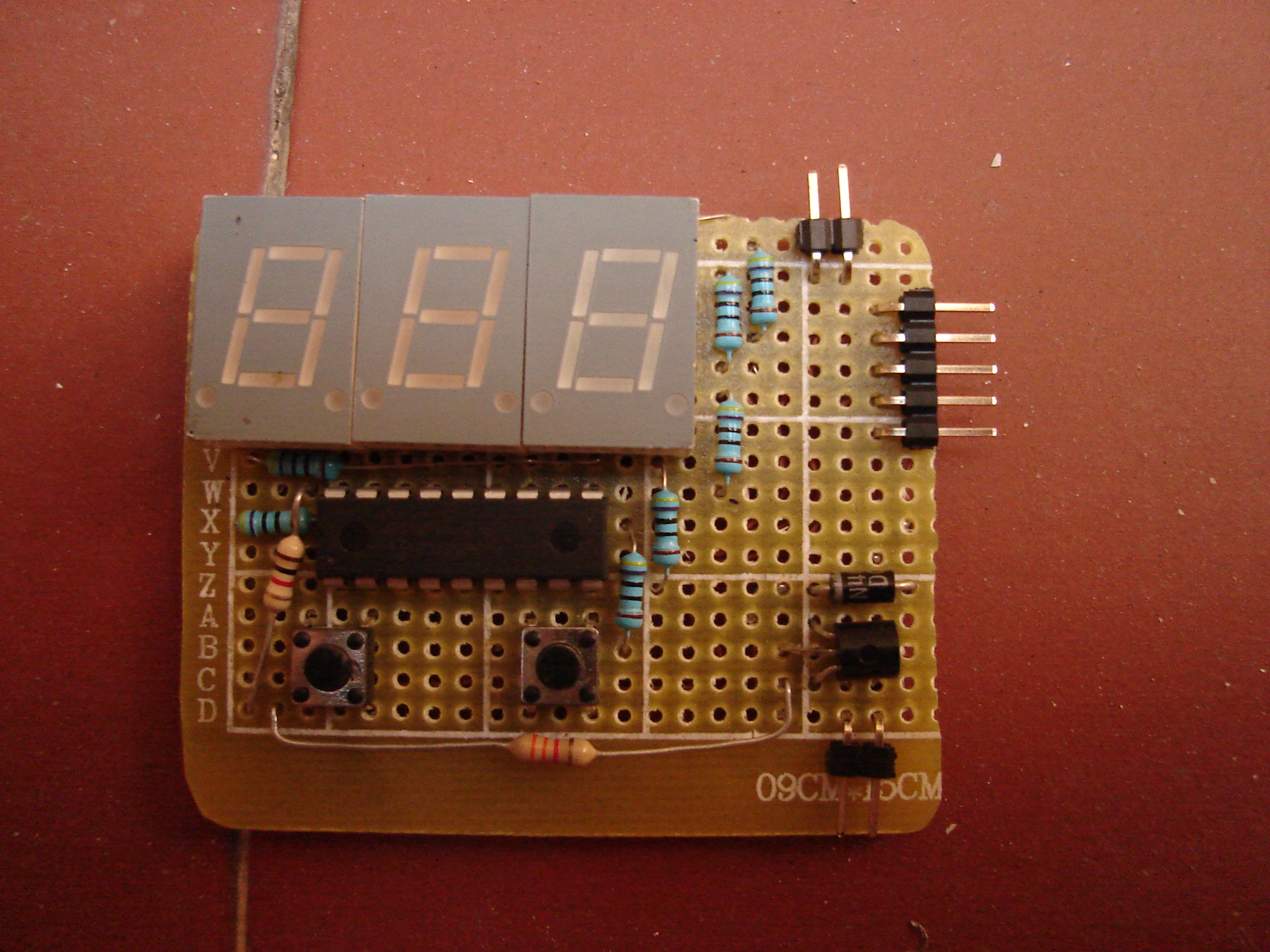
I added pinouts for the relay, power source and pic programmer.
Complete unit (nearly)
Only the power source needs a final word. I used two 5V power sources connected in series so in theory the maximum power available (based on the ratings written on the package) is 1A * 10V = 10W. I did a quick measure on the LED unit and it sucks about 5W, so the whole unit should use about 6 or 7W at most. The digital circuit runs at 5V. Be careful with the source, it uses 220V! I enclosed it in a box but it's a little dangerous because it becames very hot after 10 minutes.
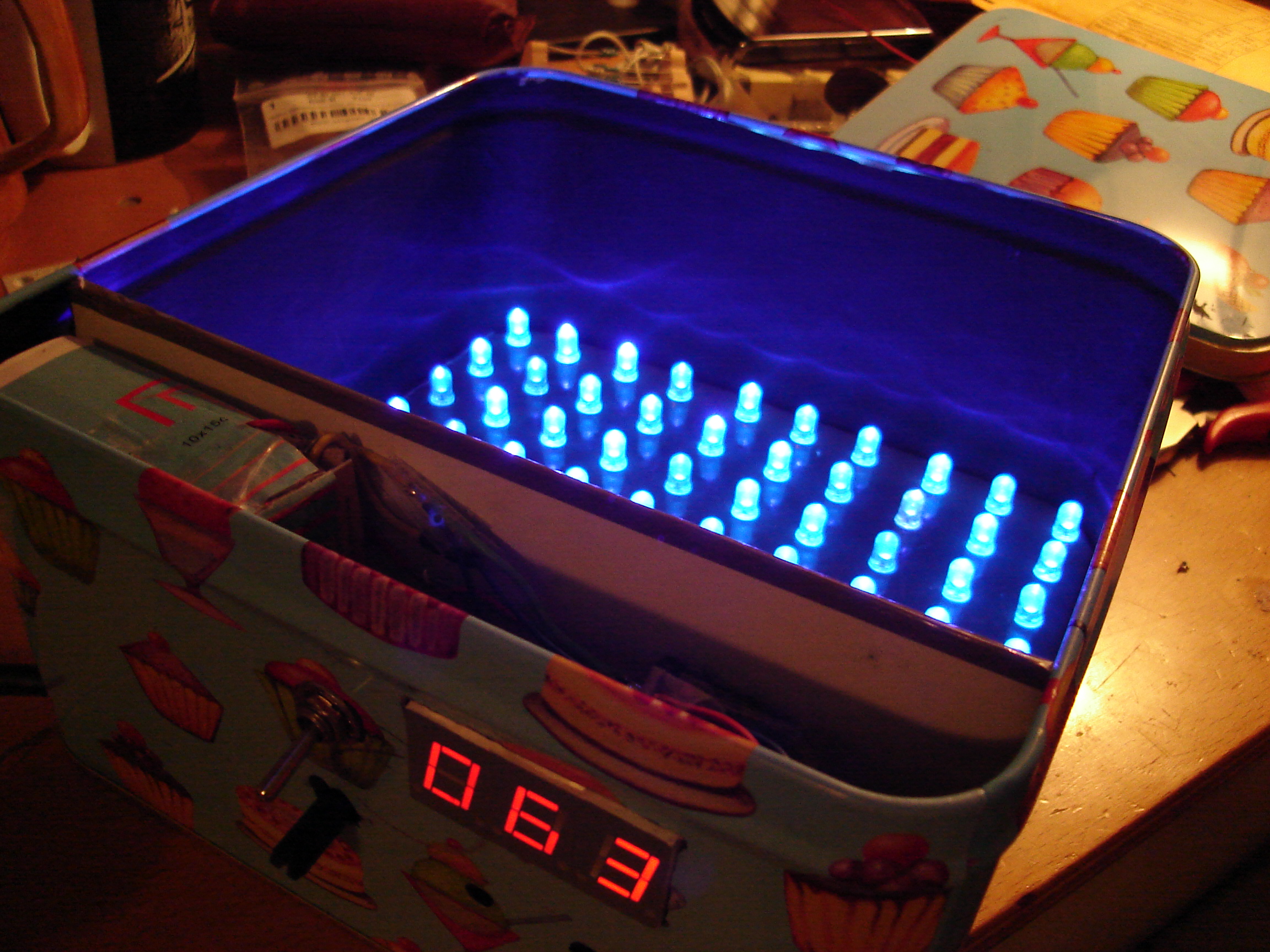
The only things that need to be done is to install the glass, paint the separator and install a diffuser to smooth the LED light, which is quite directional.
Problems
Of course I had some problems. What would be life without problems? The real problem is that I encountered them when the unit was completely mounted.
Relay oscillation
When testing the relay/timer duo with the LED unit (and the same power source) I faced a big problem, the relay switched on but after a short time (about 2ms or so) it got disconnected. My explanation for that effect was that the LED unit produced a big current peak (when switched on) which the power source couldn't manage so the digital circuit and therefore the relay received less current/voltage than expected. That is a typical problem with mechanical parts, they produce discontinuities.
The solution was to add a big capacitor (2 mF) in the 5V circuit, protecting the circuit from voltage variations. And worked! (This is usually rare in my designs) That's why is always recommened to place a capacitor on the power line, to avoid voltage variations.
EEPROM corruption
Adding the capactior added a problem. When switching off the circuit the PIC still received some power, so it continued working until the power faded out. This lead to a EEPROM corruption (maybe caused by reset and PIC malfunction at those voltages). The solution was to use the double switch (which at the moment was only used for the 220V source) by placing the capacitor between the power source and the switch, so that when I plug it off the PIC voltage reaches zero immediatly. The solution worked and now the time saved in the EEPROM doesn't get corrupted anymore.
Final notes
Isolate the 220V lines properly!!! It's very dangerous to play with high power lines. I used some rubber tube to protect all the dangerous contacts, as my box is metallic.
In theory UV light exposure is dangerous for our eyes, don't look too much. And it's dangerous for the skin too, so take care specially if you have very white skin.