E-ink display with wifi
Published: June 2016
My last electronics project has been an E-ink display that shows information over wifi. The aim of the project was:
- Create a low power wireless display to show information (think about it like a picture frame)
- That is able to run on battery for a long time
- Able to provide rich content (from many sources).
Surfing the web I found this other project: http://spritesmods.com/?art=einkdisplay by Jeroen Domburg. The project is really cool, he hacks around really cheap e-ink displays used in kindle or similar ebooks (since they are spare parts for really popular devices they are cheap) to create its own.
Getting a display
Since I didn't want to work that much (ironically I spent quite a few time in the end on this) I wen for some off-the-shelf stuff, wellI should say off-the-China really. I got this board from a random electronics supplier:
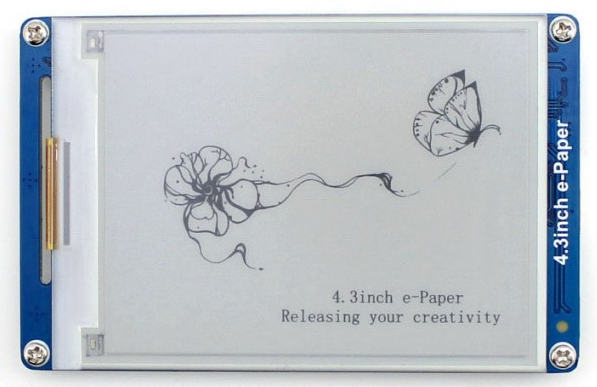
You may find it here: http://www.waveshare.com/product/4.3inch-e-Paper.htm
This board, was provided with a closed firmware blob and some random documentation and crappy chinese software to communicate with.It features:
- STM32F103ZE ARM CortexM3 SoC
- 128 MB NAND storage
- MicroSD card slot
- Some external SRAM connected to the SoC
- The e-ink display (4.3'' and 800x600 which is quite good quality)
- Some connector to talk through a UART interface @115200
For ~50$ it's quite neat, but of course I don't need much of this, actually I only need the display itself, power supplies and the connectors.
Reversing the firmware
Since it proved impossible to find a sensible datasheet for that screen I started reversing the firmware. Some other people already did some work on the screen, but it was a bit hard to fully understand their work, so I reversed the firmware anyway and I used their docs as validation and guidance. The cool thing is that I contacted the company and I managed to get a closed source blob for their driver (which was compiled with -O0 and had debug symbols!), which smoothed things significantly.
The display is quite simple, it is driven by an 8 bit data bus and a bunch of clock and latch signals. It also has 3 power domains (with different voltages) that are power gated in the board with some transistors (it turns out there is a specific power sequence for the screen to properly work). Since I don't want to mess around with the details too much I'll provide links to others' docs and my sources below.
The way the screen works is updating the screen row by row. Each update will whiten or darken the pixels of a particular row. Each pixel receives two bits which are coupled to the voltage the screen will inject to the pixel: a positive voltage will change the pixel color one way and negative voltage will do the opposite. Not injecting any voltage will result in the pixel not being changed at all, and appliyng both voltages is forbidden, haven't really tried it just in case it burns down the screen.
Display turns out to the a GDE043A:
- Some timing datasheet and power supply: http://dl.btc.pl/kamami_wa/gde043a2_ds.pdf
- Some random polish guy that does similar thing, I think the chinese guys copied some parts of his sources: http://ep.com.pl/files/10821.pdf
Hacking around the board
I easily found my way into the board, and their team was also kind to send me a nice pic on how the connections work:
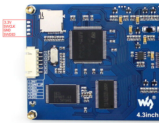
All we need is SWDIO!
Plugging the SWDIO programmer it is easy to dump the firmware using st-link. After that I could reprogram the board to show any picture I'd wanted. Next steps were to remove the NAND memory (useless to me! also the STM32 has 512KB flash!) and the micro SD socket. In the end I even stripped the white connector and I've been tempted to remove the SRAM (which used to work well but stopped at some point and I don't really know why).
The firmware I created for the STM32 is very simple: it boots, intializes the SPI interface and waits for instructions. It can either display one of the 8 flash-stored images it has (compressed using RLE) or receive an image through the SPI bus and display it. Note that since I'm not using the external SRAM I cannot fit the image in the 64KB RAM, since it's 800x600 pixels image at 2bpp (4 colors!). That is 117KB that I don't have, for that reason the image format supported is RLE compressed. The image format is quite simple and decompression happens as the CPU feeds data to the screen (since we don't have room to decompress the image!), that results in a fairly inefficient process, particularly since the image has to be decompressed 4 times (this is because the darkest color requires 4 "darken" pulses and drawing is performed sequentially).
Adding the ESP8266
Any project needs an ESP8266 to be cool, doesn't it? So here it is! The ESP8266 is responsible to do the following tasks:
- Boot the whole thing and decide what to do
- Create an access point for configuration if config is lost
- Connect to the AP and download a new image
- Keep config and sleep while not refreshing the screen: make sure current draw is close to zero!
Since we want it to run on a battery for months the ESP8266 will use the deep sleep mode to cut down consumption to the micro-watt range. To avoid the board and the STM32 to draw power I added a small power gating transistor so the whole board is powered off while not updating the screen. Cool things about e-ink screens: they don't need any power to display images!
The ESP8266 will download the image, power up the board, and send the data through SPI. I used UART for a while and I was having issues with it. I thought it was the SDK that was adding extra output to the UART FIFO but it turned out to be the server, sending chunked responses! Stupid me that was too late and I've already implemented SPI. On the bright side SPI is very fast: decided to use 4MBps for data transfers.
Putting it all togheter
Soldering and gluing things on the back of the board looks like this:
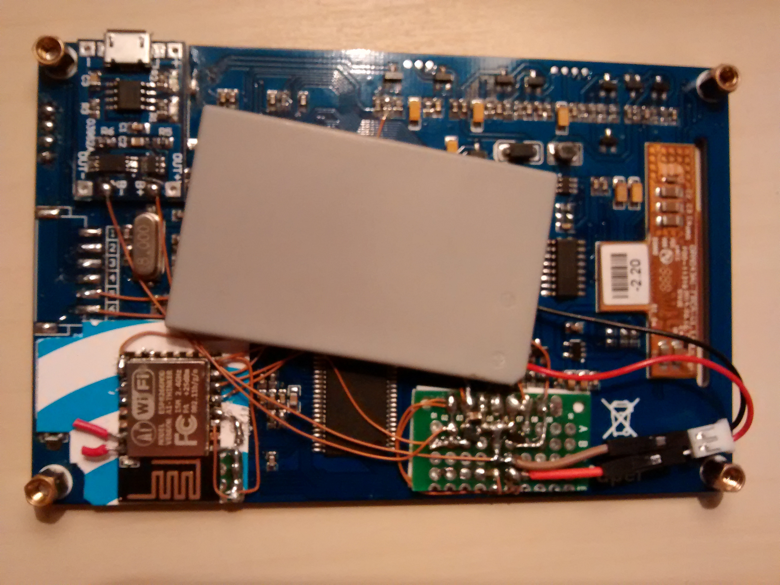
The ESP8266 can be found in the bottom left corner, with some cabled that connect it to the STM32 and the misc board on its right. That green board contains some pullups and the power transistor. It also contains an MCP1700T used to lower the battery voltage for the ESP. It turns out the ESP doesn't really need it since it tolerates 4.5V or over, but just in case... A LiPo battery charger is added and glued so the battery can be easily charged through a micro-usb cable. I glued the battery to the STM and the result is pretty nice, the board it's around 1cm thick and it's only missing a transparent back board to cover everything.
Server software
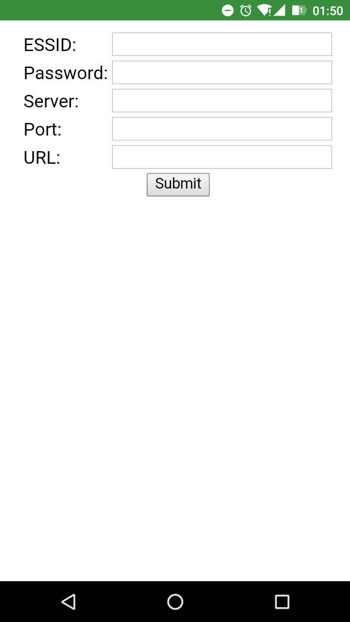
The configuration for the device it very easy. Connect the battery (I need to add a proper switch!) and you'll get this screen:
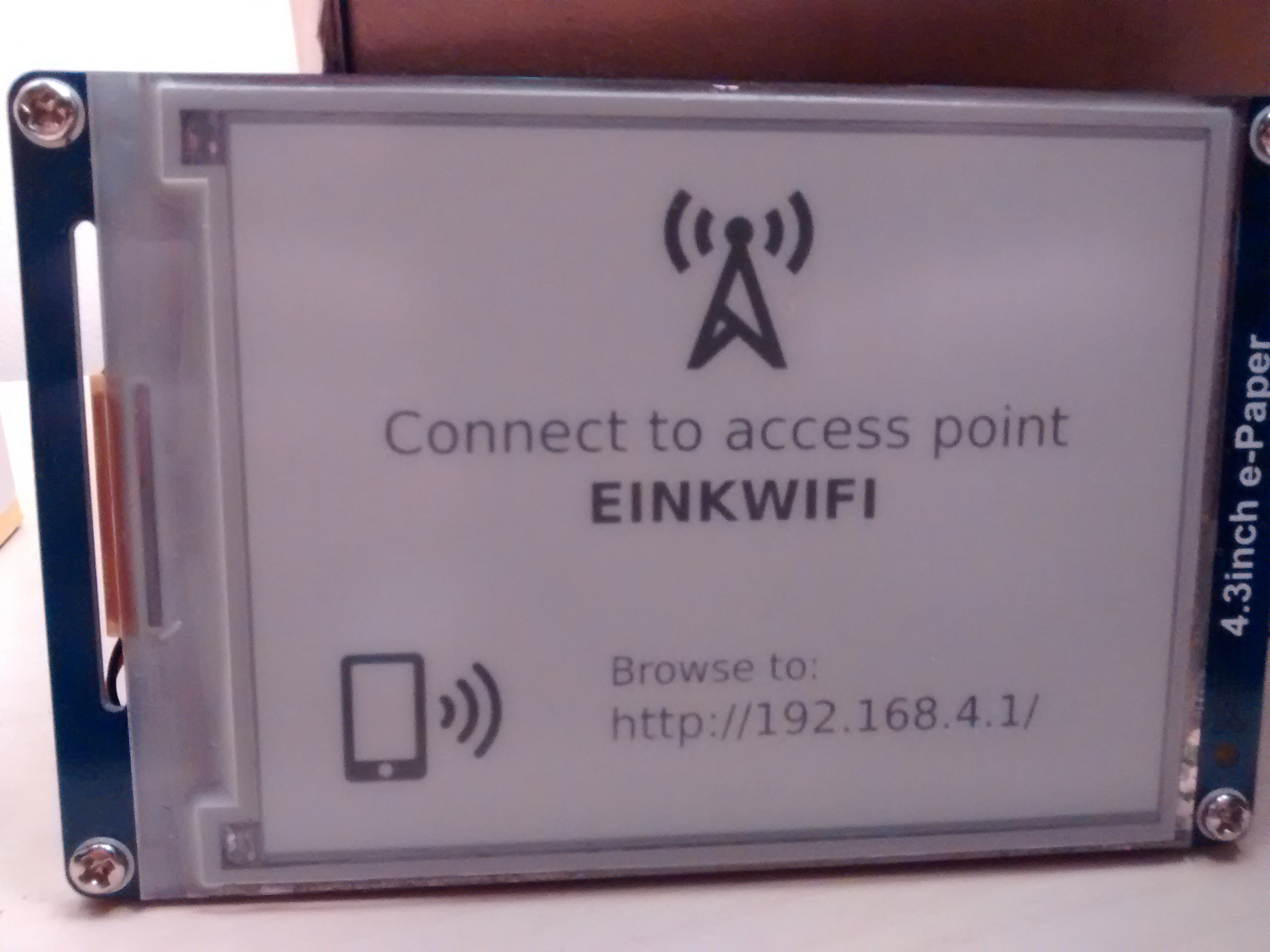
Using your cellphone you can easily navigate to the IP and fill in the form:
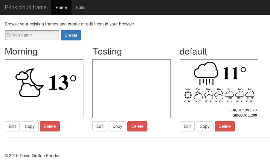
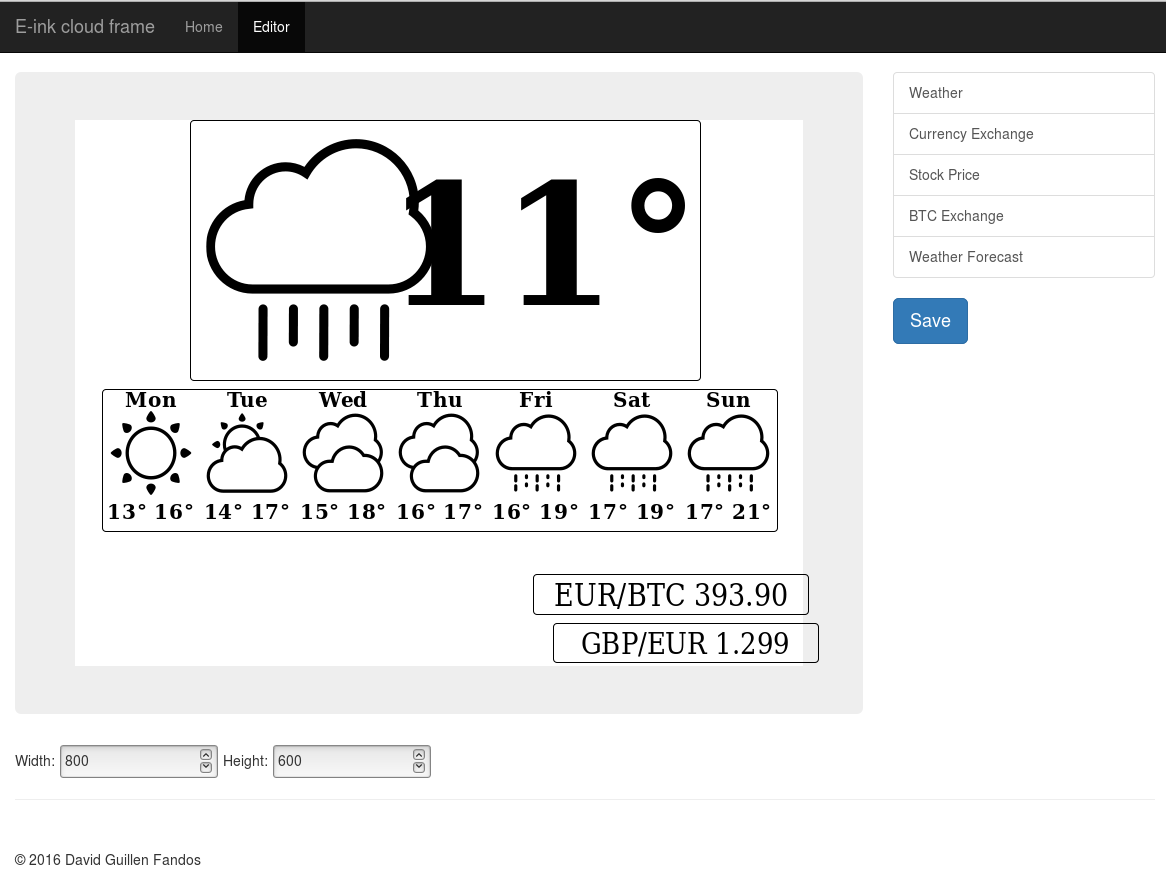
After that your screen will happily update itself and show you whatever you decied to display. To design your screen you may use the server softare (a bunch of PHP scripts) that present a cool website where you can add and tweak widgets:
The designer allows to customize the screen like this:
Final result
Yeah most of you didn't read any of the above (or maybe you did it!). Check out the final result:
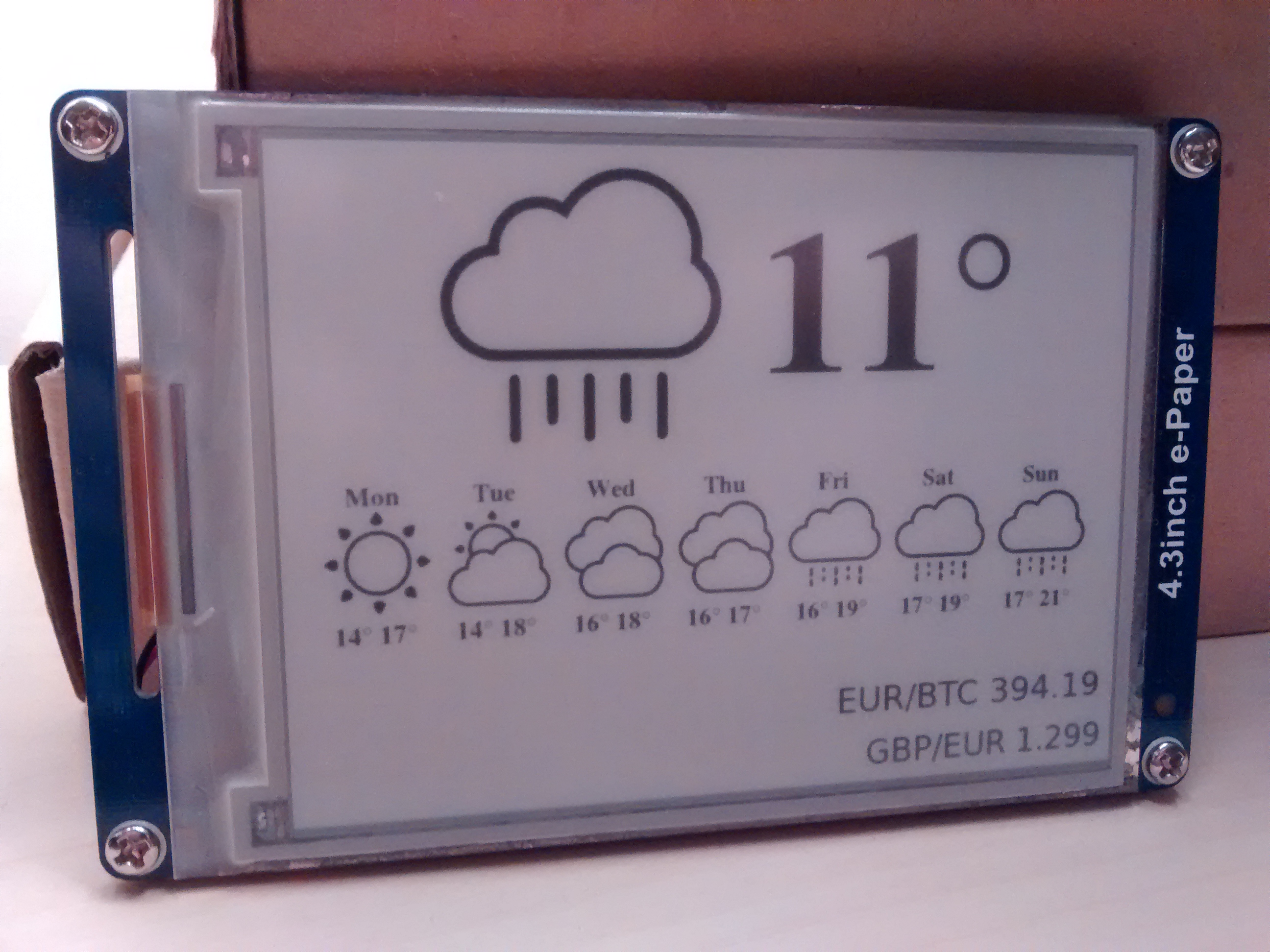
I've got it standing on my bed table. I'll have to come up with more useful widgets I guess. Good news is that writing a new widget takes 10 minutes and around 50 lines of PHP code :) Hope you liked it!
You might find the github repo for the software bits at: https://github.com/davidgfnet/wifi_display
TODO
- Add LDR to turn off updates at night
- Measure current draw somehow, at least battery life!
- Cool to also measue battery voltage and detect low bat.
Update 2017
Since many people mailed me for this, here it goes, the "original" source/pre-compiled bits of FW that the chinese screen runs.