Acrylic RGB clock with BT support
Published: March 2023
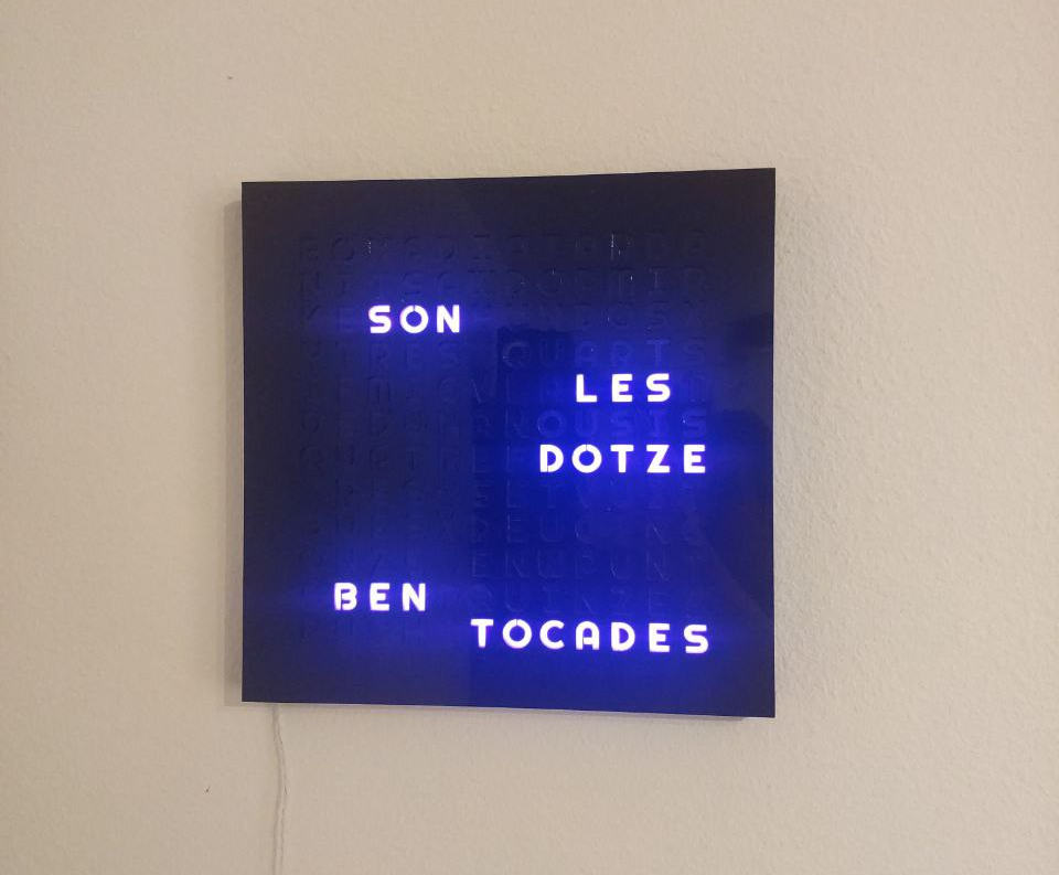
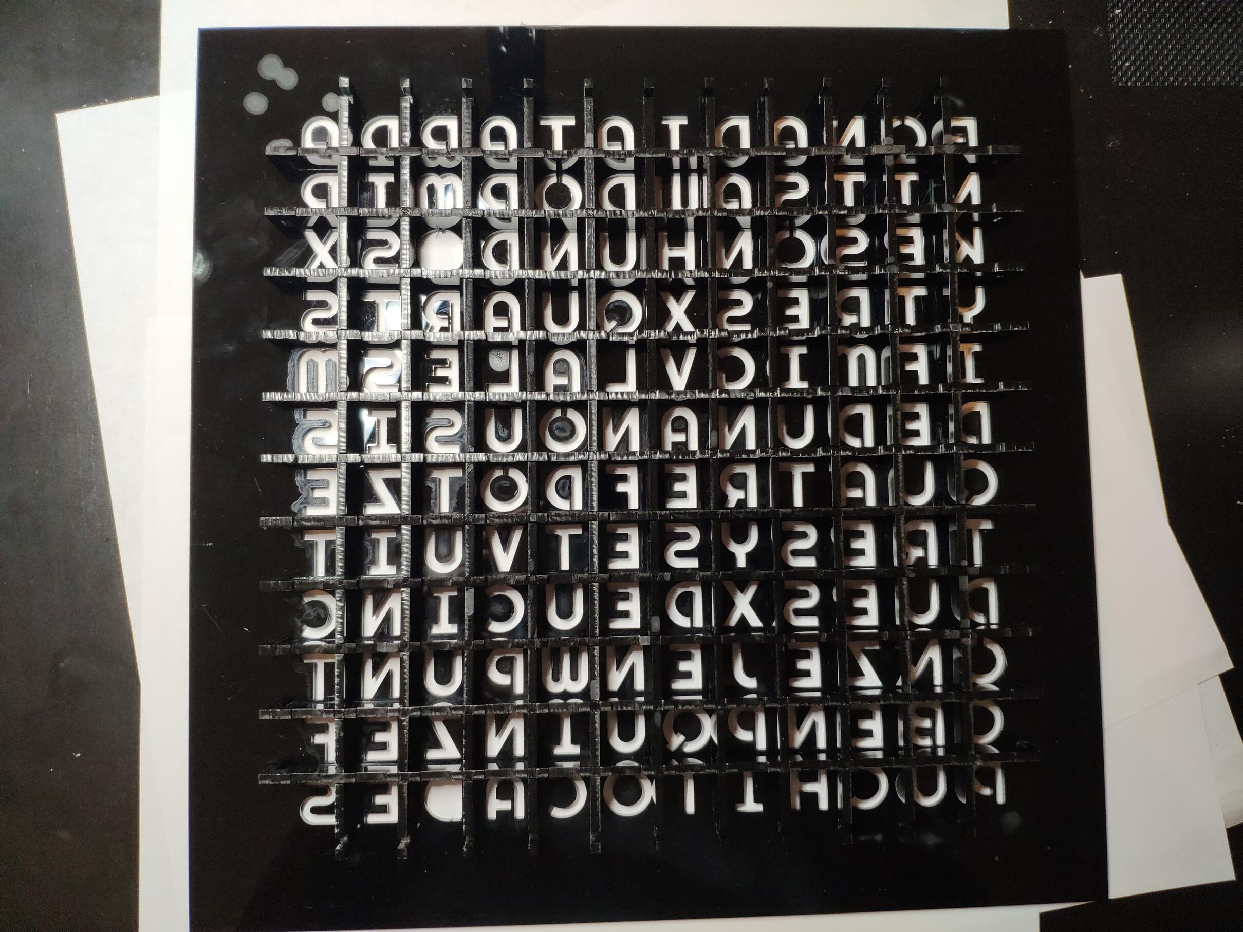
I didn't come up with the idea for the clock. These kinds of clocks have existed for a while and I shamelessly took the idea and built my own version of it. The clock can display the approximate time using eight possible sentences, which correspond to quarter hours and half quarters (including some funny wording for o'clock times and "half quarter past").
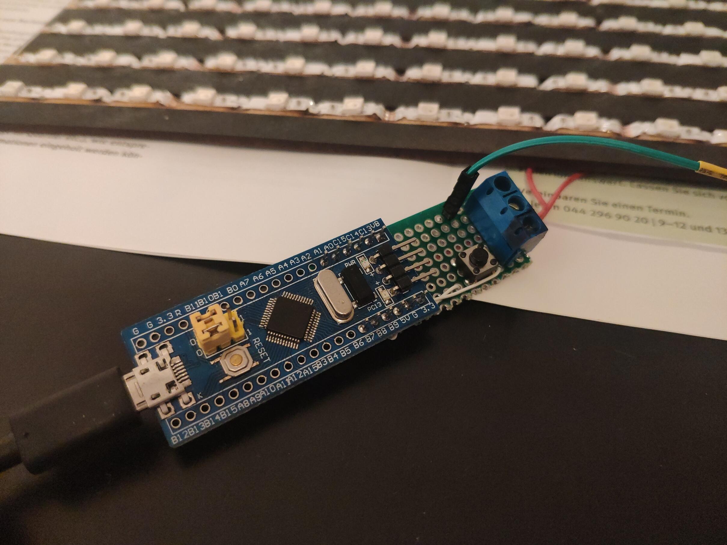
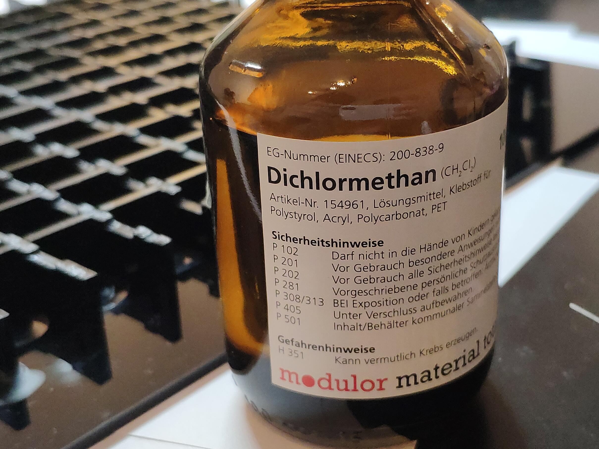
The clock was built using acrylic and a laser cutter, assembled toghether using dichloromethane to fuse parts toghether and lit using an RGB LED strip. The brains of the operation is an STM32 "Bluepill" and a BLE serial module.
You can find the code for the project in Github
Building the clock
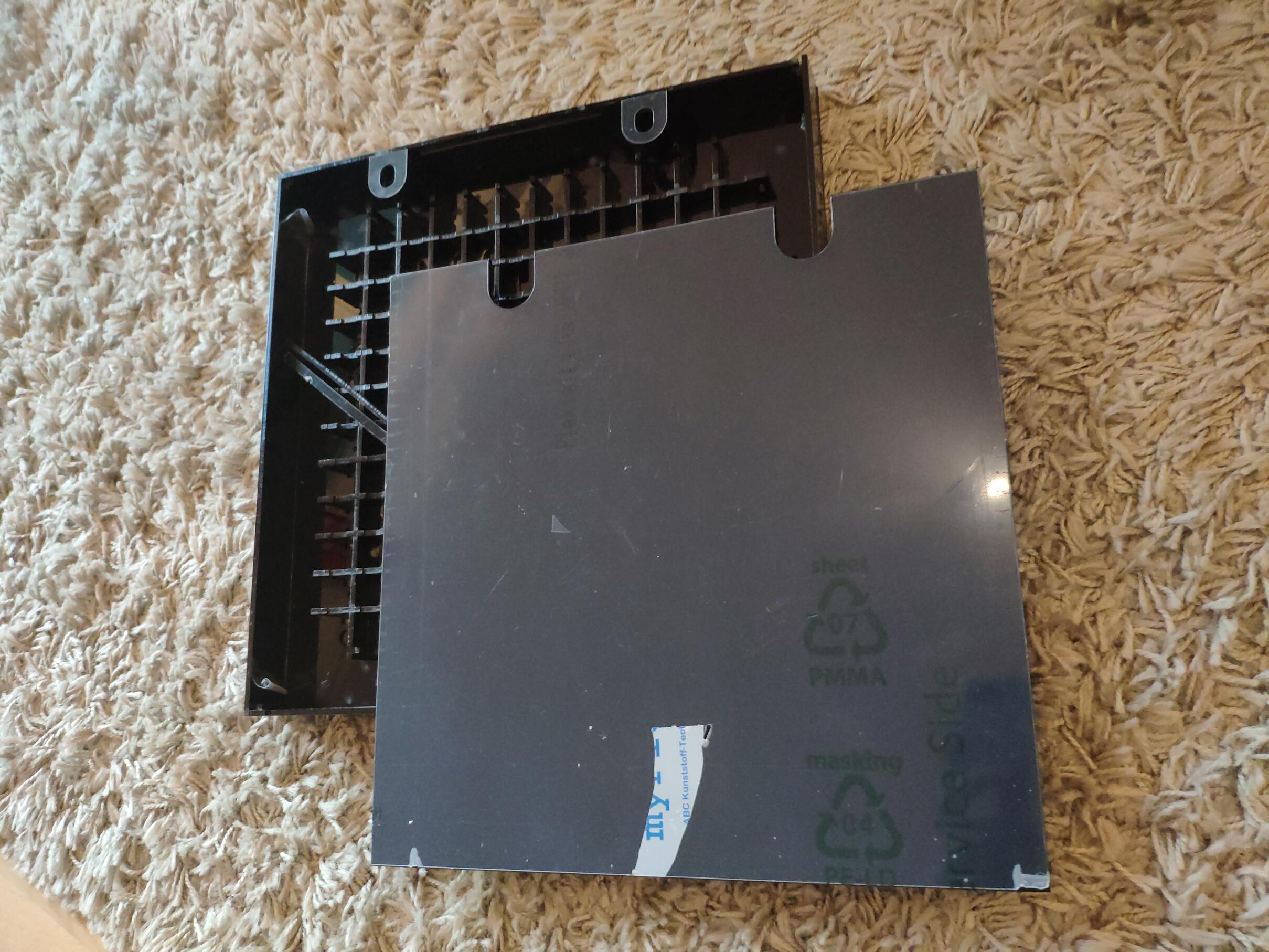
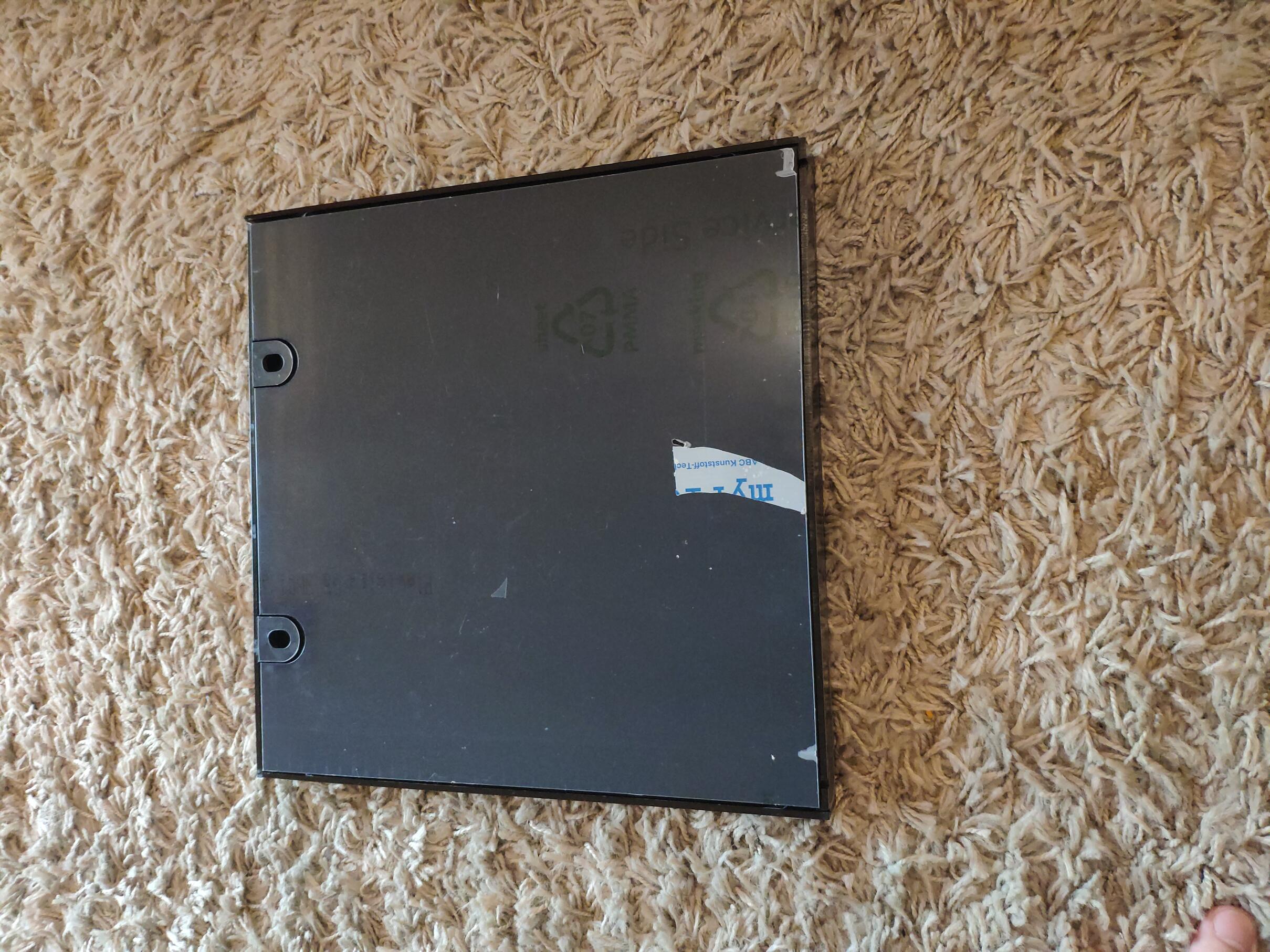
The clock is made out of black acrylic in 6 big pieces: front (with cutout for letters), back (with some hanging holes) and four side panels. The panels are attached to the front panel and the back panel can be removed. The hanging holes are glued to the frame using some smaller acrylic pieces. The back panel is held toghether with some acrylic parts that prevent it from falling (it slides in) and a couple of strong magnets.
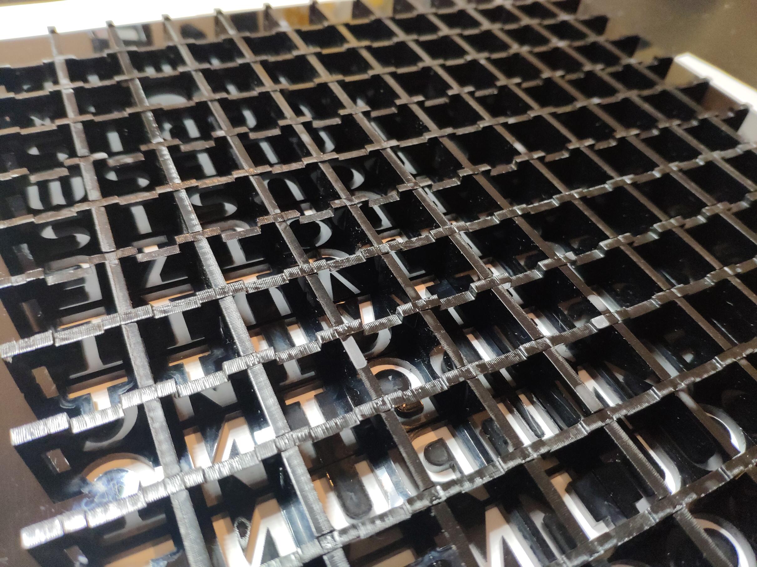
Internally, there's a grid of black acrylic parts separating character into boxes, to prevent light leaks. This is also fused to the front plane. In these boxes I placed milky-white acrylic to act as diffusers. In the end I ended up using several layers of acrylic: semi transparent layer, followed by a couple of transparent acrylic layers with some diffuser self-adhesive paper. This was tedious to glue but in the end it paid off (the text is much more readable!).
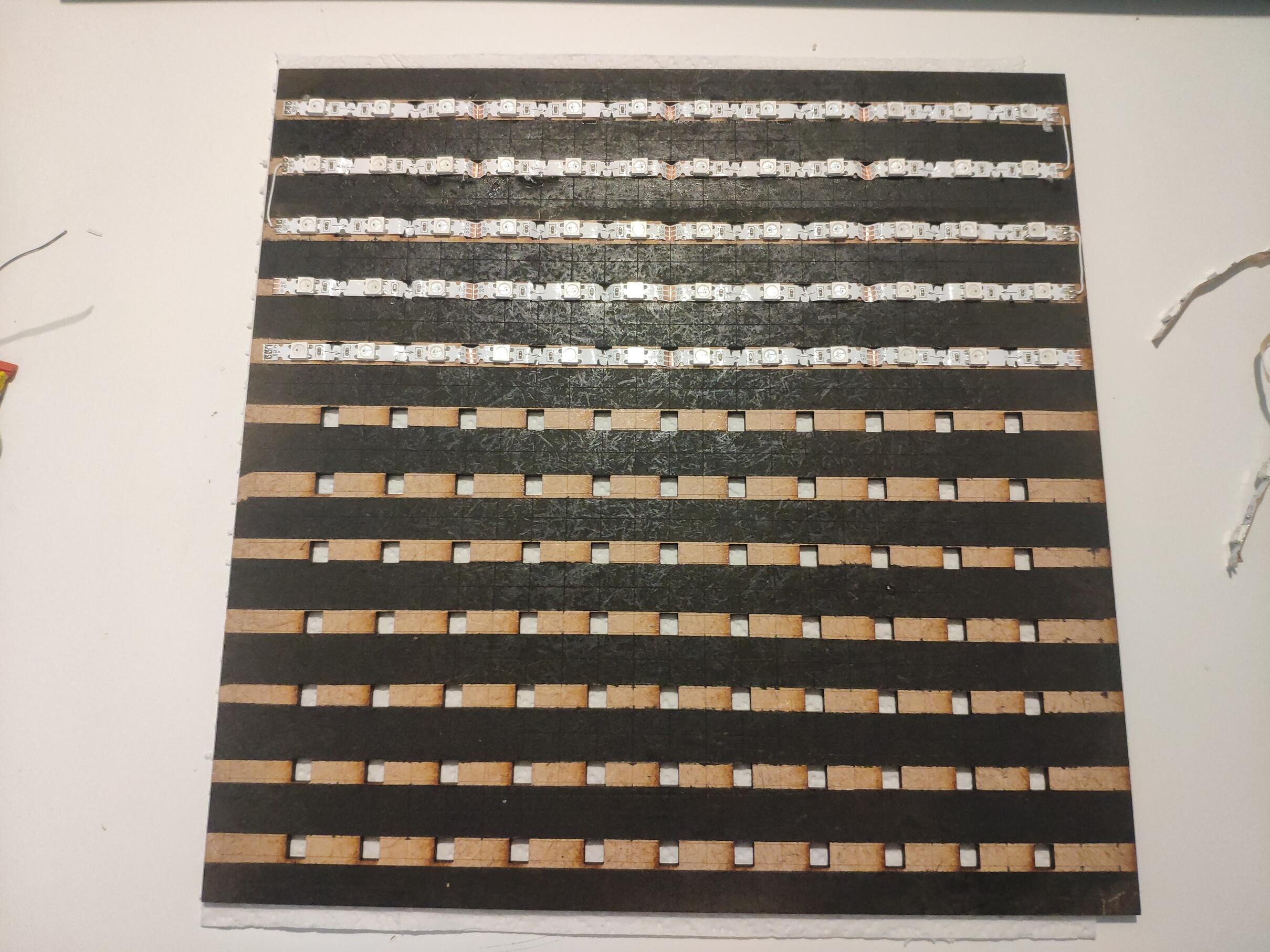
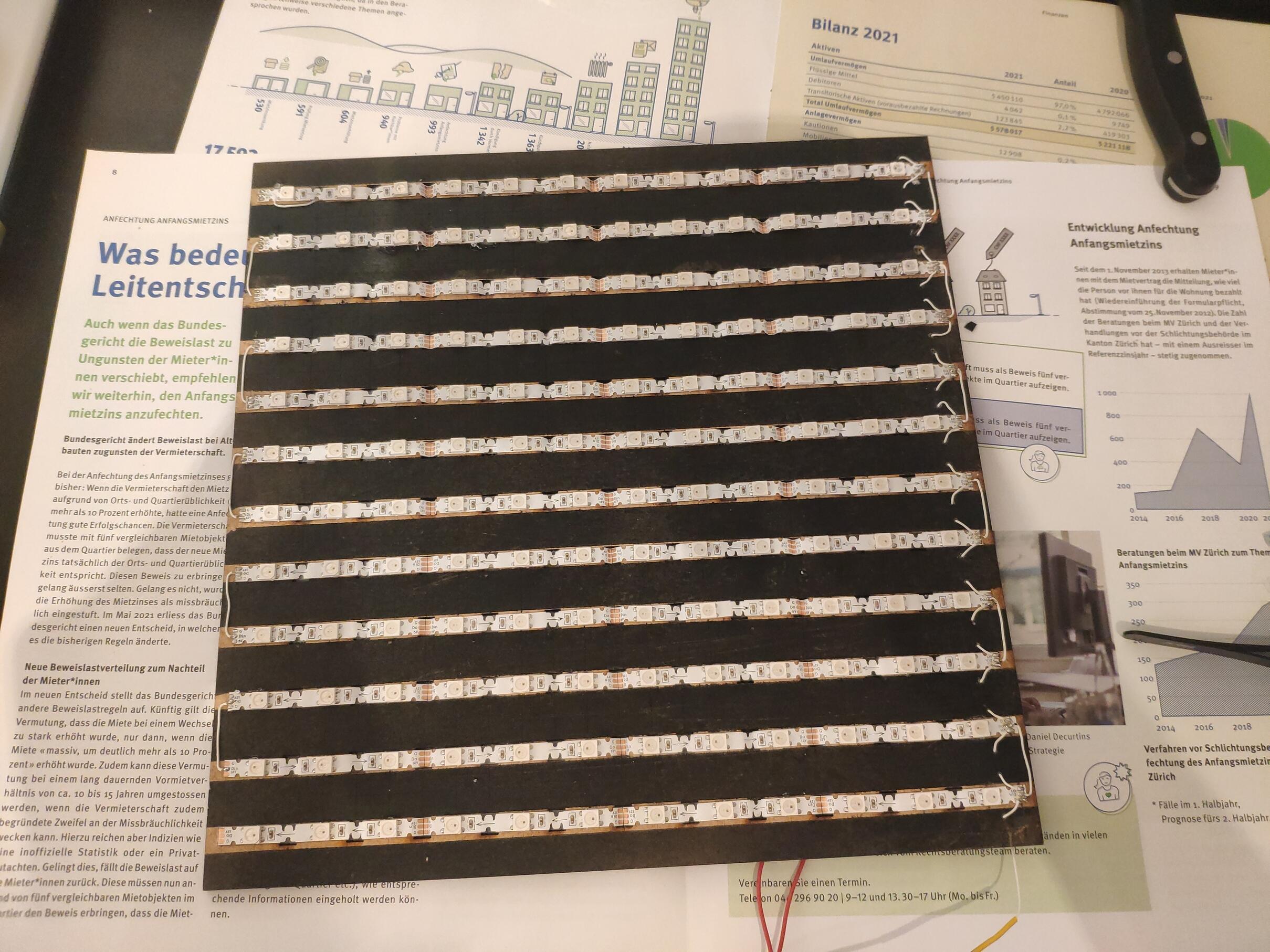
On top of these grid I place a piece of wood (painted in black) where the LEDs live. They are just glued to the wood using the self-adhesive the strip comes with. The panel is held toghether using a sliding mechanism and a couple of rubber bands. The back of the panel is great to wire the LED power and data rails.
There's a small hole at the bottom where a very thin white cable comes out. The original idea was to use battery power, but the math didn't add up (even with big batteries it wouldn't last that long).
Design choices
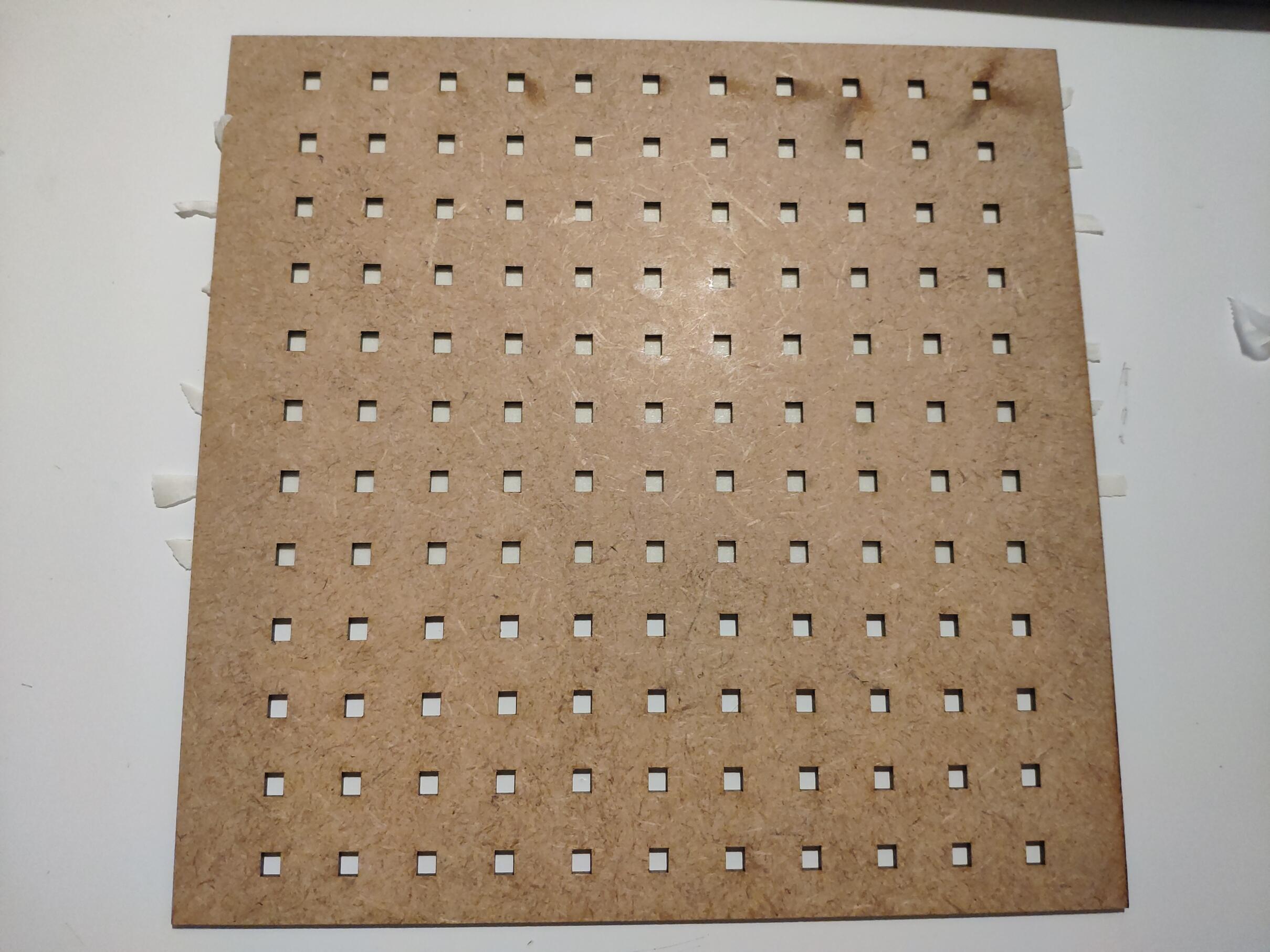
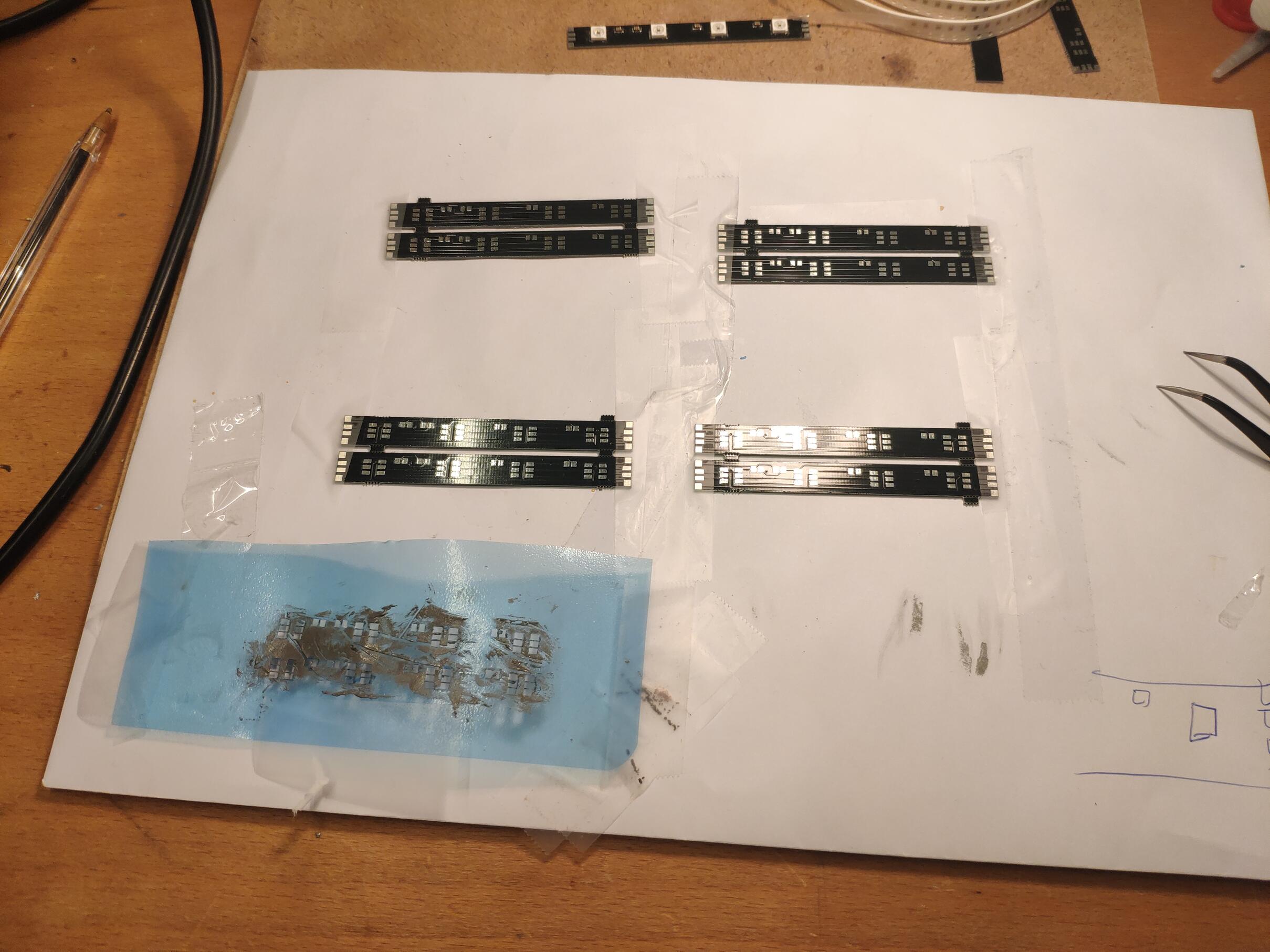
Initally I designed the LED supports using a custom PCB, since the LED separation was not "standard" (was hard to find a LED strip that would fit). Each letter has a box size of around 20 by 20 millimiters and there are 12 by 12 columns and rows. This would require an LED strip of 50 LEDs per meter, which seems quite rare on Ebay/Aliexpress. For this reason I decided to create a small PCB and solder the LEDs myself.
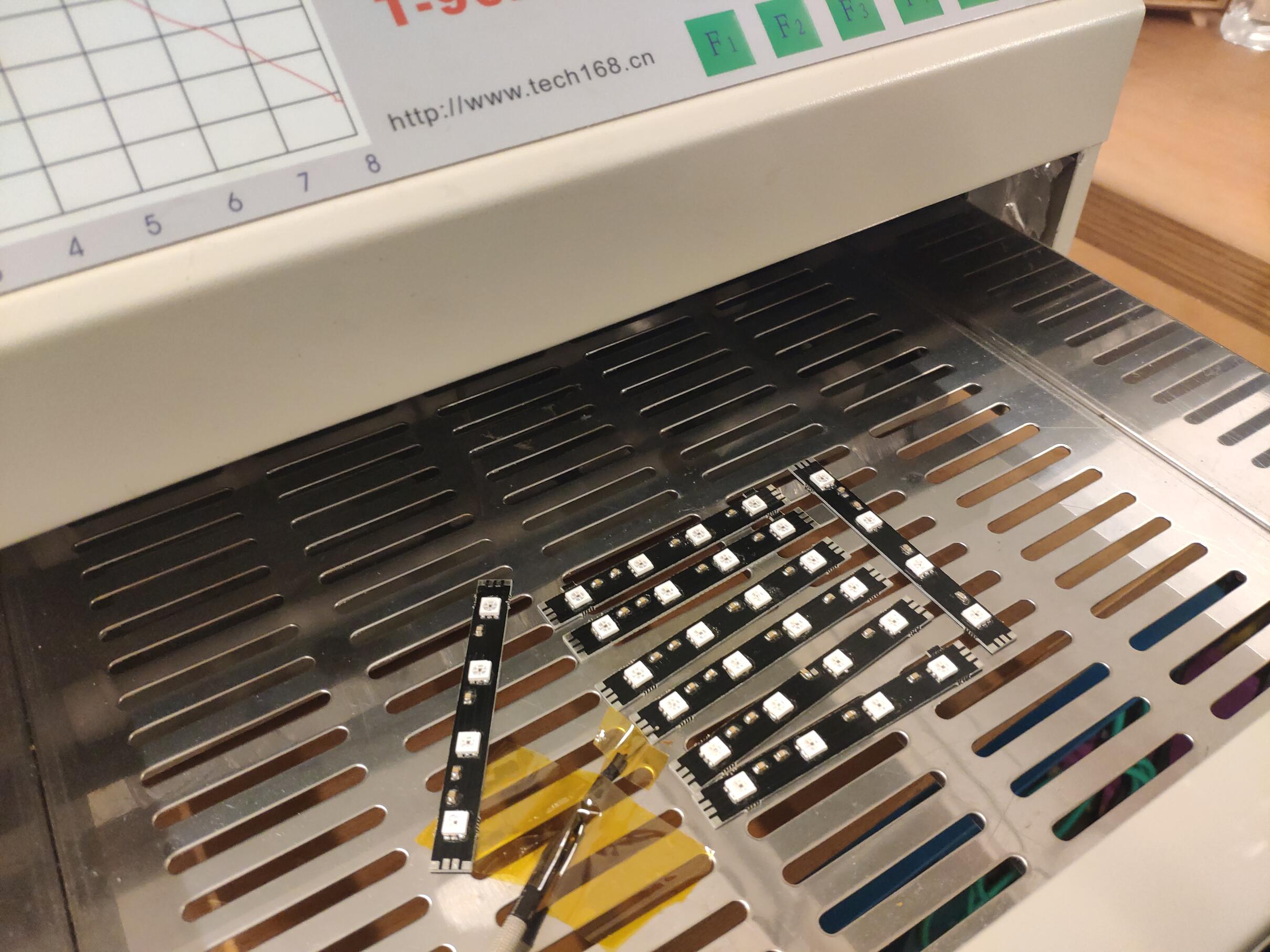
The obvious choice was APA102 LEDs: they support an SPI-like protocol which simplifies software support and requirements. However this did not work as expected: the LEDs were of questionable quality and resulted in many strips not working as expected and having too many dead LEDs. I suspect their reflow soldering temperature is not great and they just die during the baking periods.
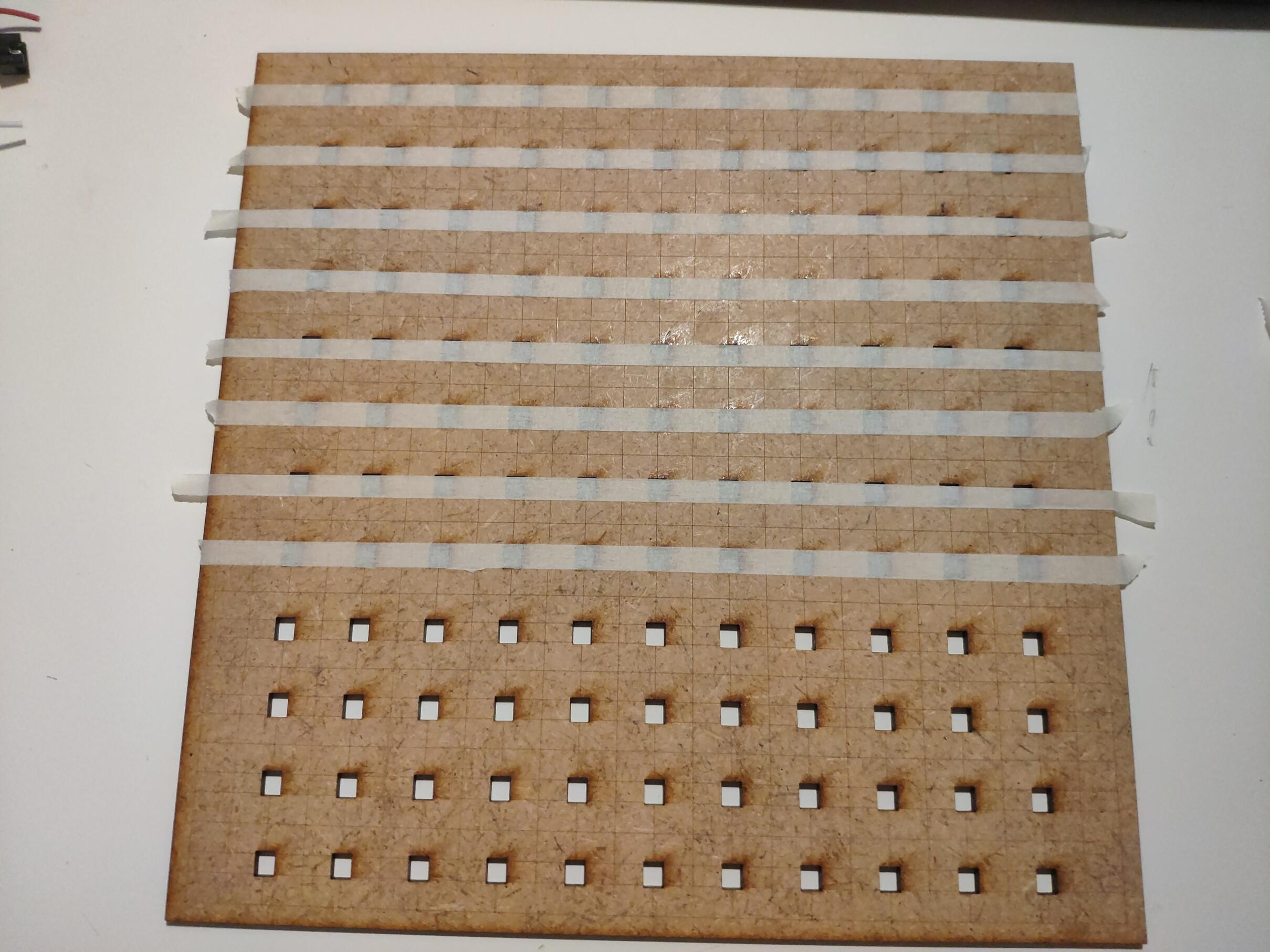
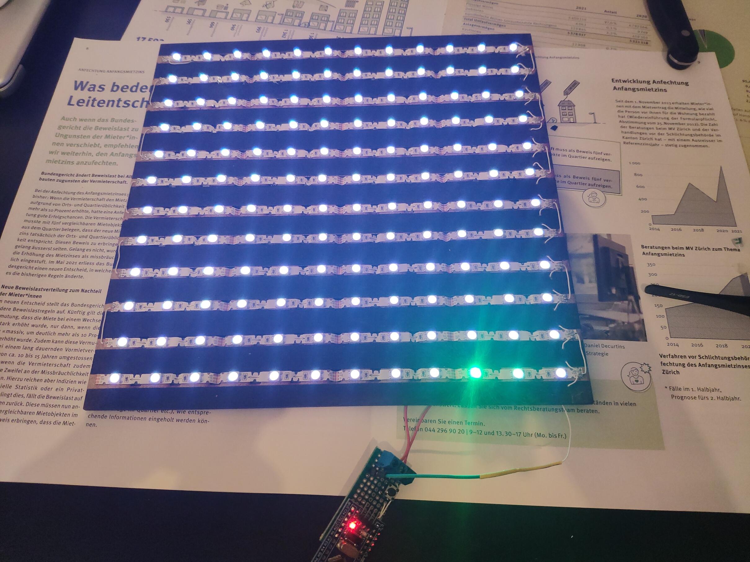
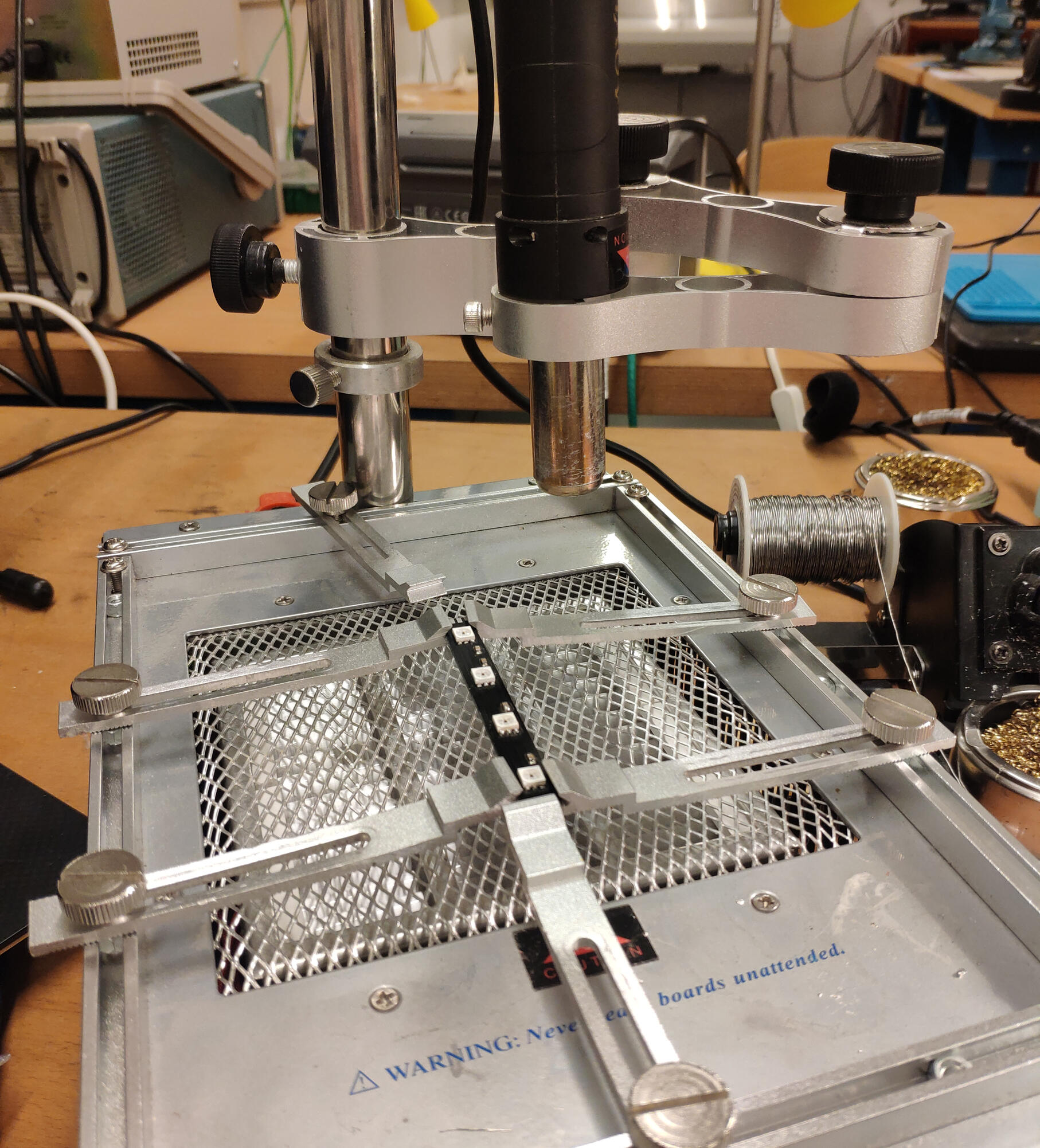
In the end I ended up picking WS8212B due to being widely available in many shapes and colors. In order to "fit" them to the 20mm spacing that I needed, I got a 48 LED per meter strip (spaced at 20.8mm) and compressed them a bit so that they were a bit closer. For that I glued them to a wood panel with some small holes through which I could slightly bend the strip. This was surprisingly easy and did the trick (it was also much cheaper and easier to do!)
Driving WS8212B LEDs
The microcontroller is responsible for: keeping time using its RTC, refreshing the LED strip, handling the BLE module (connected via its UART) and (optionally) serving USB requests to the host computer. This last bit is really for convenience, so that I could test and upgrade the firmware from my laptop.
Initally I grabbed the WS8212B datasheet, and proceeded to bit-bang the required 1-wire signal to drive the LEDs. This works well even though the signal was quite bad (timing wise), it seems the WS8212B is very forgiving. However, when I added the UART to the equation, it blew up. It is impossible to keep serving the UART interrupts while driving the LEDs (the UART ISR takes too much time), and disabling IRQs during refresh is not a good idea (it takes around 4ms to update the 144 LEDs, which is too long and we can lose incoming UART data).
The solution to the driving problem is to offload it to the microcontroller, and for that I used SPI. The idea is simple (and seems that others had already used this trick successfully!) and easy to implement: use the SPI driver to generate the required waveform. Even though the SPI controller is not designed to produce the required waveforms, we can see it as a digital function generator that pushes pulses at a regular frequency. The SPI engine coupled with the STM32's DMA controller can push very long bit sequences with no silent times (it seems the DMA controller pushes the next byte while the SPI is still sending the previous one).
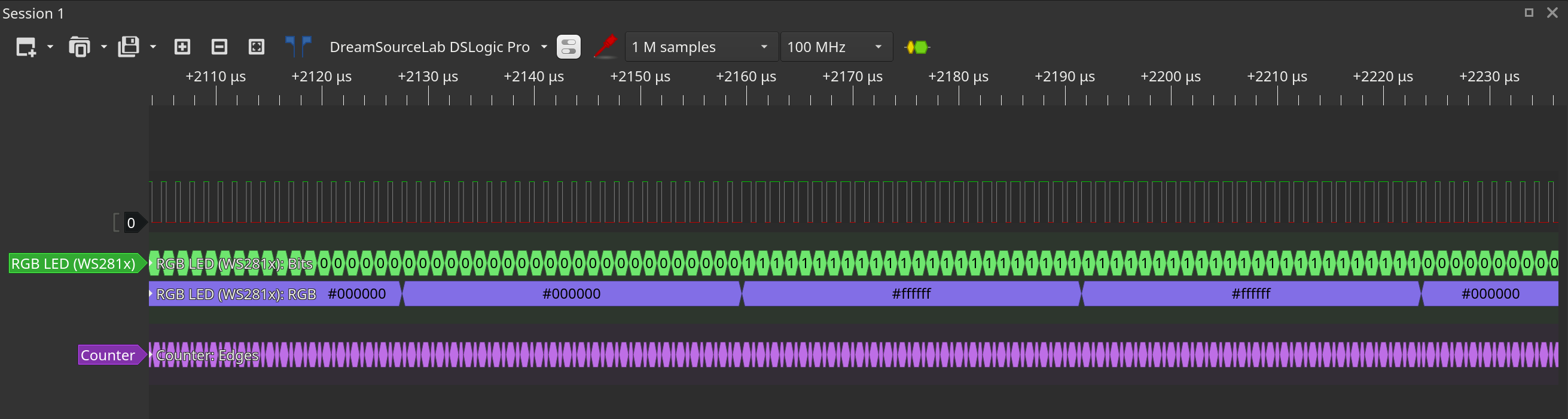
Since the WS8212B uses two similar waverforms for 0 (400ns high, 800ns low) and 1 (800ns high and 400ns low), we can see each symbol as three bits (100 and 110). For this we need to pick an SPI frequency of 1/400ns (2.5MHz) and "convert" our messages by expanding each bit into a 3 bit sequence. The STM32 allows only a handful frequencies for the SPI master; we picked 2.25MHz, which is 72MHz / 32. This works very well even though the frequency is 10% off.
You can see it working below. Funnily enough PulseView has a WS8212B decoder that parses the colors for you. That helps debugging.
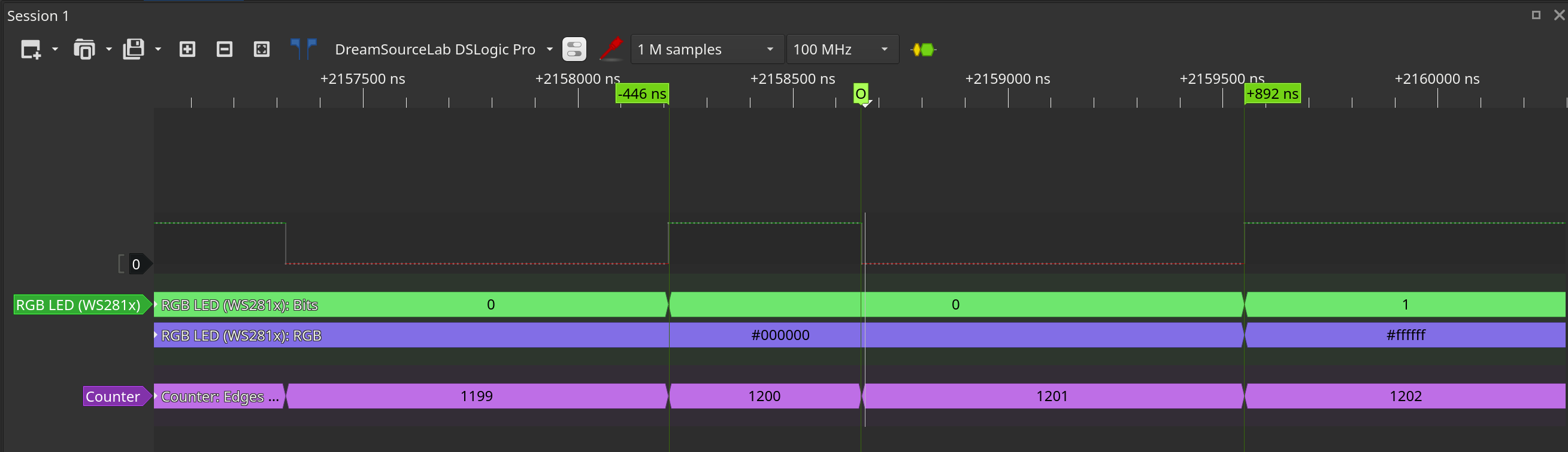
With this we can now offload most of the work (USART, SPI, USB) to interrupts and use the CPU to calculate time, colors and even LED animations.
Meet BLE and WebBluetooth
I wanted some Bluetooth support but then realized that I would need to write an Android app to control it, which I hate (yeah Google changes the whole ecosystem every couple years). But then I came across WebBluetooh! Which... unfortunately only supports Bluetooth Low Energy, which is pretty much another completely different standard.
In the end I ended up buying a JDY-19 module (BLE) and using that instead. They are cheap and easy to find: a couple of UART pins to communicate, and implement a serial protocol on the BT's side. This allowed me to create a website instead, which is much faster and usable. Works only on Chrome/Chromium but it works well on all OSes (Android, Linux, etc).
BLE allows to send and receive payloads of around 20 bytes, since BLE packets are rather small. On top of this protocol I added some framing using only ASCII characters (not sure how compatible other modules are, but I wanted this to be very compatible with most BLE modules out there) which allows me to send longer packets in a reliable way (added header, checksum, etc).
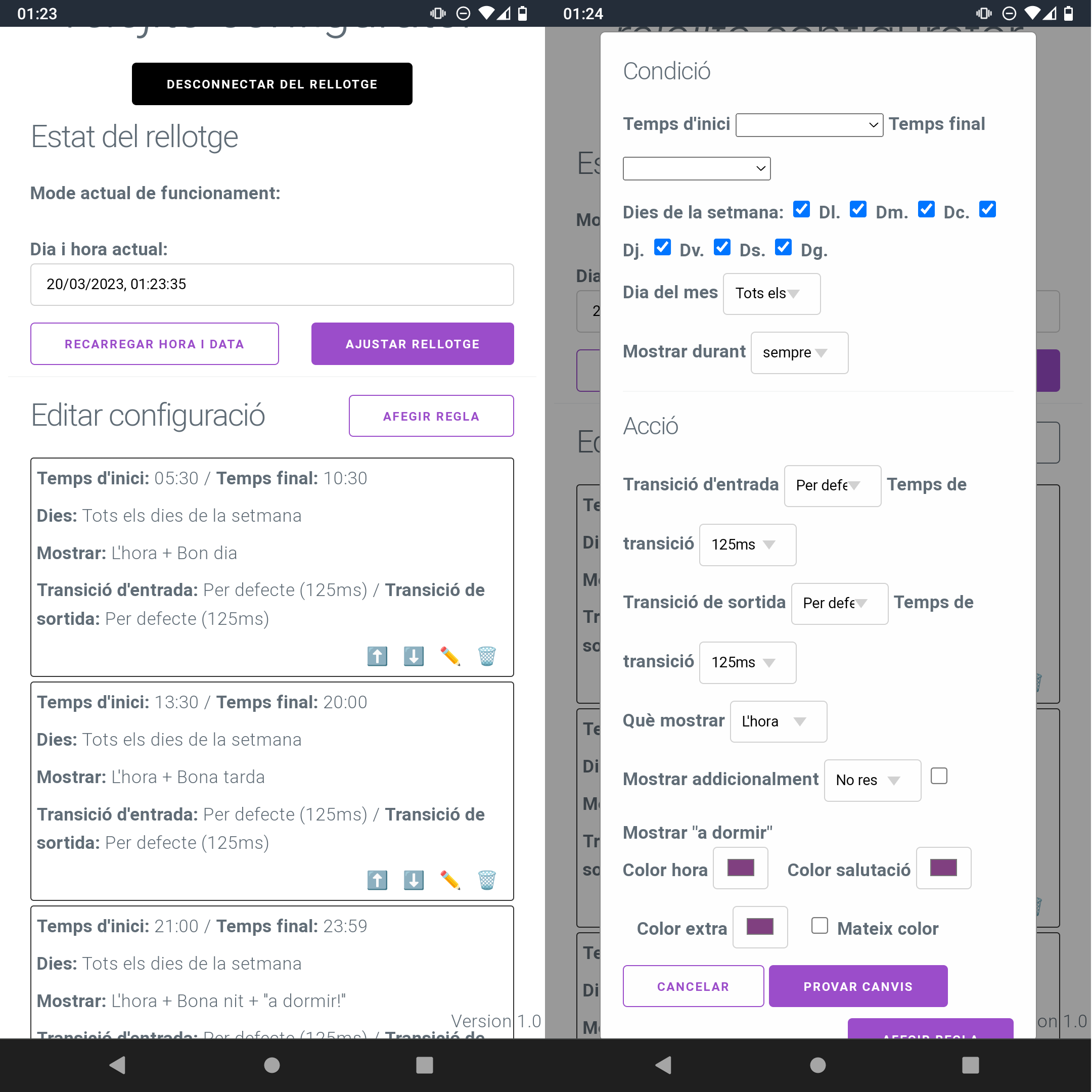
The website is rather simple. It allows to set/read the clock time, change how it displays the time, etc. It has a simple yet usable rule-based system where we can customize what the clock shows depending on the time of day (or even calendar). The config is pushed via BLE and flashed to the clock for residency. Since the STM32 has a small battery, it can keep configuration and time even when unplugged, allowing us to unplug it when we want total darkness in the room.